ORIENTAL MOTOR U.S.A. Corp.
570 Alaska Avenue
Torrance, CA 90503
1-800-GO-VEXTA (468-3982)
ORIENTAL MOTOR U.S.A. Corp.
570 Alaska Avenue
Torrance, CA 90503
1-800-GO-VEXTA (468-3982)
| Lead Time1 | - {Contact your local sales office for more information.} |
Motor Type |
- Brushless DC Motor |
Motor Frame Size |
- 3.54 in. |
Output Power |
- 120 W (1/6 HP) |
Power Supply |
- Single-Phase 100-120 VAC |
Shaft/Gear Type |
- Hollow Shaft Flat Gearhead |
Gear Ratio (X:1) |
- 15 :1 |
Output Shaft Diameter |
- 20 mm |
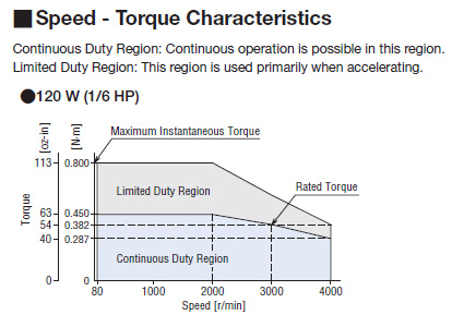
Rated Torque |
- 50 lb-in |
Electromagnetic Brake |
- Not Equipped |
Variable Speed Range (r/min) |
- 5.3 ~ 267 |
Permissible Load Inertia |
- 2300 oz-in²*When instantaneous stop or instantaneous bi-directional operation is performed = 1230 oz-in² |
Permissible Radial Load |
-
0.39 in. from Shaft End = 290 0.79 in. from Shaft End = 240 lb |
Permissible Axial Load |
- 112 lb |
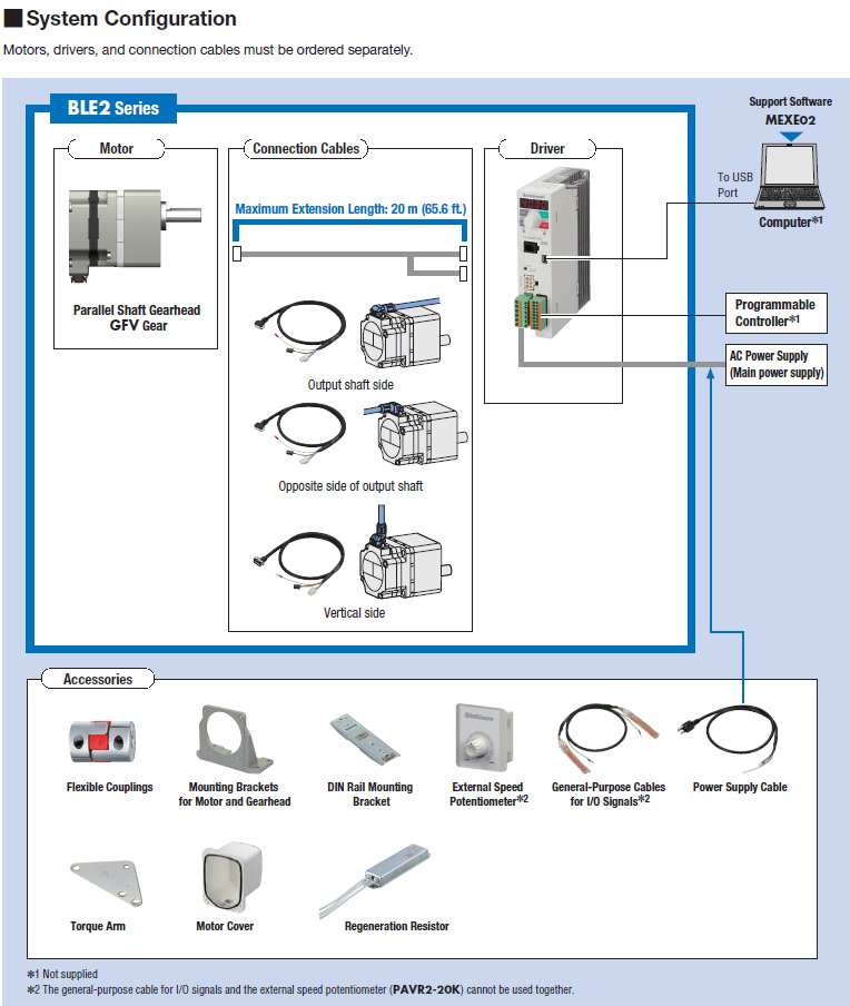
Max. Extension Length |
- 10.50 |
Components |
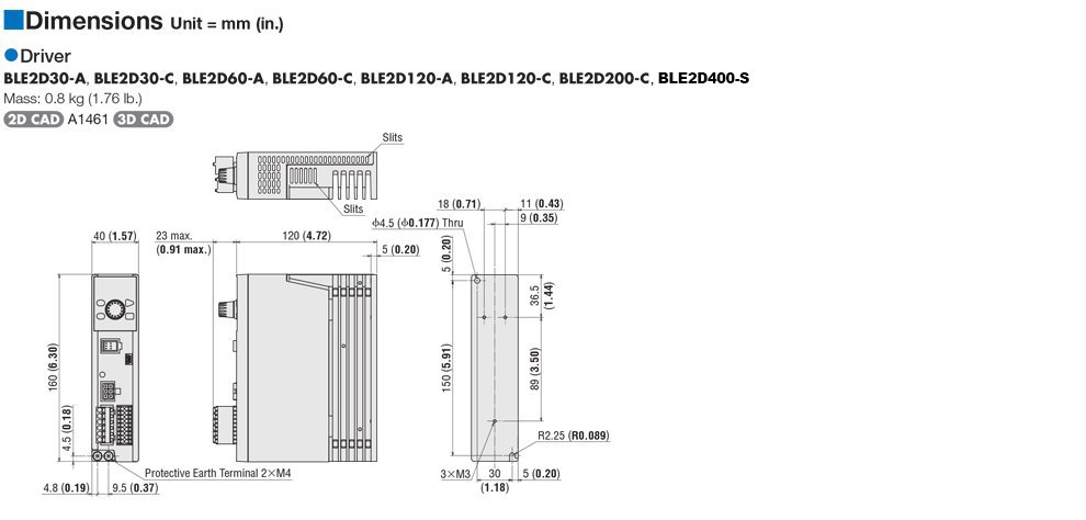
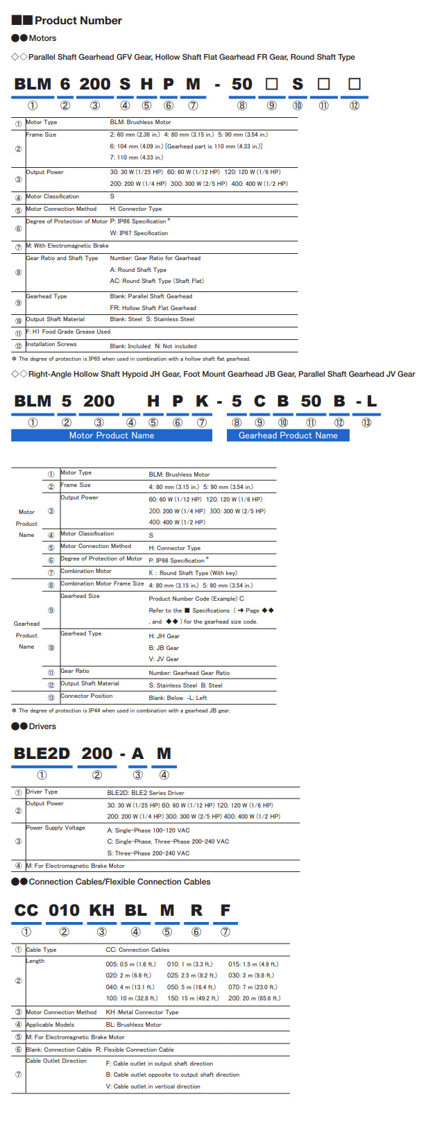
- BLM5120HP-GFV [Motor] BLE2D120-A [Driver] GFS5G15FR [Gearhead] |
RoHS Compliant |
- These products do not contain substances that exceed the regulation values in the RoHS Directive. |
Safety Standards |
- UL CSA CE |
CE Marking |
- Low Voltage Directives EMC Directives |
Insulation Resistance (Motor) |
- 100 MΩ or more when 500 VDC megger is applied between the windings and the case after continuous operation under normal ambient temperature and humidity. |
Insulation Resistance (Driver) |
- 100 MΩ or more when a 500 VDC megger is applied between the power supply terminal and the protective earth terminal and between the power supply terminal and the I/O signal terminal after continuous operation under normal ambient temperature and humidity. |
Dielectric Strength (Motor) |
- Sufficient to withstand 1.5 kVAC at 50 Hz applied between the windings and the case for 1 minute after continuous operation under normal ambient temperature and humidity. |
Dielectric Strength (Driver) |
- No abnormality is judged even with application of 1.5 VAC at 50 Hz between the power supply terminal and the protective earth terminal and with application of 1.5 kVAC at 50 Hz between the power supply terminal and the I/O terminal for 1 minute after continuous operation under normal ambient temperature and humidity. |
Temperature Rise (Motor) |
- The maximum temperature rise of the windings is 90ºF (50ºC) and that of the case is 72ºF (40ºC) when measured by the thermocouple method after rated continuous operation under normal ambient temperature and humidity. |
Temperature Rise (Driver) |
- Temperature rise of the heat sink is 90ºF (50ºC) or less measured by the thermocouple method after rated continuous operation under normal ambient temperature and humidity. |
Ambient Temperature Range |
- 32ºF ~ 104ºF (0ºC ~ 40ºC), nonfreezing |
Ambient Humidity |
- 85% or less, noncondensing |
Altitude |
- Up to 3300 ft (1000 m) above sea level. |
Operating Atmosphere |
- No corrosive gases or dust. Cannot be used in a radioactive area, magnetic field, vacuum or other special environment. |
Thermal Class |
- CSA standards: 105 (A), EN standards: 120 (E) UL |
Degree of Protection |
-
[Motor] IP65 [Driver] IP20 |
Speed Control Method (Select one of the following) |
-
Digital Setting:
Analog Setting:
|
Number of Speed Settings |
- Max. 16 points (Factory setting: 4 points) |
Acceleration/Deceleration Time |
- 0.0 ~ 15.0 s (Factory setting: 0.5 s) |
Torque Limiting |
-
Analog Setting: 0.1 ~ 15.0 s (Time setting from stopped state until reaching rated speed) Common setting for acceleration/deceleration time with the use of acceleration/deceleration time potentiometer*. Digital setting: 0.0 ~ 15.0 s (Time setting from current speed to setting speed) Individual settings for acceleration time/deceleration time for each operating data*. *Acceleration time/deceleration time varies with the load condition of the motor. |
Input Signals |
-
Photocoupler Input method Input Resistance: 5.7 kΩ Operation by internal power supply: 5 VDC Connectable External DC Power Supply: 24 VDC -15~+20% Current 100 mA or more Sink input/Source input Supplied through external wiring. Arbitrary signal assignment to X0~X2 input (3 points) is possible [ ]: Initial Setting [FWD], [REV], [MO], ALARM-RESET, EXT-ERROR, H-FREE. |
Output Signals |
-
Photocoupler and Open-Collector Output External Power Supply: 4.5 ~ 30 VDC Current 100 mA or less Sink output/Source output Supplied through external wiring. Arbitrary signal assignment to Y0, Y1 (2 points) is possible [ ]:Initial Setting [ALARM-OUT1], [SPEED-OUT], ALARM-OUT2, MOVE, VA, WNG |
Protective Function |
-
When the following protective functions are activated, ALARM-OUT1 output turns OFF and the motor will undergo a coasting stop. At the same time, the alarm code will be displayed. (Instantaneous stop for external stop only) Overcurrent, Main circuit overheating, Overvoltage, Undervoltage, Sensor error, Overload, Overspeed, EEPROM error, Initial sensor error, Initial operation inhibition, External stop |
Time Rating |
- Continuous |