| Items |
 /Asset/pke564mc-img.jpg /Asset/pke564mc-img.jpg PKE564MC 2.36 in. (60 mm) 5-Phase Stepper Motor with Brake (AC Input) Web Price $327.00
|
/Asset/pke564mc-img.jpg PKE566MC 2.36 in. (60 mm) 5-Phase Stepper Motor with Brake (AC Input) Web Price $333.00
|
/Asset/pke564mc-img.jpg PKE569MC 2.36 in. (60 mm) 5-Phase Stepper Motor with Brake (AC Input) Web Price $339.00
|
 /Asset/pke564mc-hs_-img.jpg /Asset/pke564mc-hs_-img.jpg PKE564MC-HS50 2.36 in. (60 mm) 5-Phase Geared Stepper Motor with Brake (AC Input) Web Price $1,466.00
|
/Asset/pke564mc-hs_-img.jpg PKE564MC-HS100 2.36 in. (60 mm) 5-Phase Geared Stepper Motor with Brake (AC Input) Web Price $1,466.00
|
|||||
| Text Description | ||||||||||
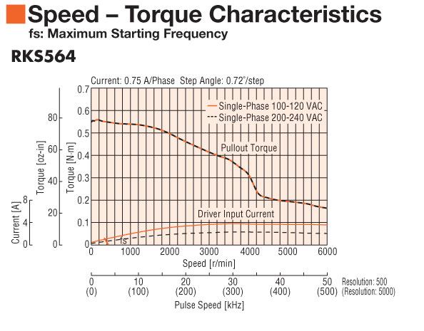
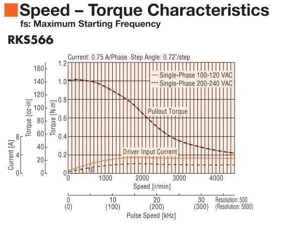
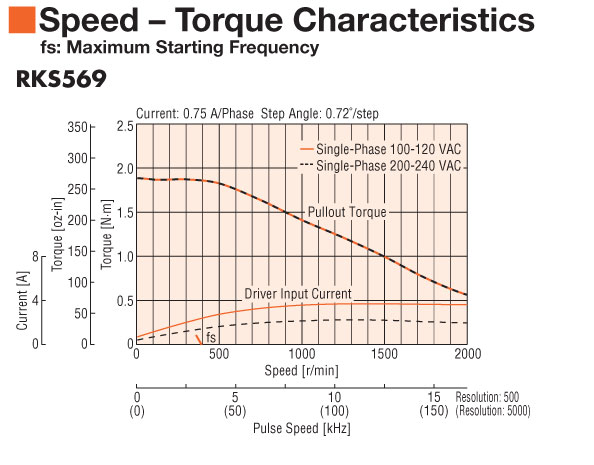
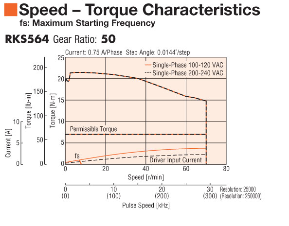
| Frame Size | 2.36 in60 mm | |||||||||
| Motor Length | 1.91 in.48.50 mm | 2.34 in.59.5 mm | 3.50 in.89 mm | 1.91 in.48.50 mm | 1.91 in.48.50 mm | |||||
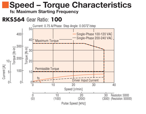
| Speed-Torque Characteristics |
 |
 |
 |
 |
 |
|||||
| Holding Torque | 73 oz-in0.52 N·m | 136 oz-in0.96 N·m | 250 oz-in1.77 N·m | 976 oz-in7 N·m | 1408 oz-in10 N·m | |||||
| Type | Standard | Standard | Standard | Geared | Geared | |||||
| Shaft/Gear Type | Round Shaft with Flat (No Gearhead) | Round Shaft with Flat (No Gearhead) | Round Shaft with Flat (No Gearhead) | Harmonic Gear | Harmonic Gear | |||||
| Gear Ratio (X:1) | 50 :1 | 100 :1 | ||||||||
| Backlash | ||||||||||
| Encoder Resolution | ||||||||||
| Shaft | Single | |||||||||
| Electromagnetic Brake | Equipped | |||||||||
| Current | 0.75 A | |||||||||
| Basic Step Angle | 0.72º | 0.72º | 0.72º | 0.0144º | 0.0072º | |||||
| Permissible Speed Range (r/min) | 0 ~ 70 | 0 ~ 35 | ||||||||
| Rotor Inertia | 1.75 oz-in²320x10-7 kg·m² | 2.4 oz-in²430x10-7 kg·m² | 3.8 oz-in²700x10-7 kg·m² | 1.94 oz-in²355x10-7 kg·m² | 1.94 oz-in²355x10-7 kg·m² | |||||
| Lost Motion | 0.7 arc min maximum | 0.7 arc min maximum | ||||||||
| Permissible Overhung Load | 0 in. from Shaft End = 20 lb0.2 in. from Shaft End = 22 lb0.39 in. from Shaft End = 29 lb0.59 in. from Shaft End = 40 lb0.79 in. from Shaft End = 66 lb0 mm from Shaft End = 90 N5 mm from Shaft End = 100 N10 mm from Shaft End = 130 N15 mm from Shaft End = 180 N20 mm from Shaft End = 270 N | 0 in. from Shaft End = 20 lb0.2 in. from Shaft End = 22 lb0.39 in. from Shaft End = 29 lb0.59 in. from Shaft End = 40 lb0.79 in. from Shaft End = 66 lb0 mm from Shaft End = 90 N5 mm from Shaft End = 100 N10 mm from Shaft End = 130 N15 mm from Shaft End = 180 N20 mm from Shaft End = 270 N | 0 in. from Shaft End = 20 lb0.2 in. from Shaft End = 22 lb0.39 in. from Shaft End = 29 lb0.59 in. from Shaft End = 40 lb0.79 in. from Shaft End = 66 lb0 mm from Shaft End = 90 N5 mm from Shaft End = 100 N10 mm from Shaft End = 130 N15 mm from Shaft End = 180 N20 mm from Shaft End = 270 N | 0 in. from Shaft End = 72 lb0.2 in. from Shaft End = 83 lb0.39 in. from Shaft End = 99 lb0.59 in. from Shaft End = 123 lb0.79 in. from Shaft End = 162 lb0 mm from Shaft End = 320 N5 mm from Shaft End = 370 N10 mm from Shaft End = 440 N15 mm from Shaft End = 550 N20 mm from Shaft End = 720 N | 0 in. from Shaft End = 72 lb0.2 in. from Shaft End = 83 lb0.39 in. from Shaft End = 99 lb0.59 in. from Shaft End = 123 lb0.79 in. from Shaft End = 162 lb0 mm from Shaft End = 320 N5 mm from Shaft End = 370 N10 mm from Shaft End = 440 N15 mm from Shaft End = 550 N20 mm from Shaft End = 720 N | |||||
| Permissible Thrust Load | 2.2 lb9.80 N | 2.60 lb11.80 N | 3.70 lb16.70 N | 101 lb45 N | 101 lb45 N | |||||
| Encoder Output | ||||||||||
| Safety Standards | UL CE | |||||||||
|
|
||||||||||